L-Tek Dance Pad Lisek Mod - getting your pad ready for Tech
- Intro
- Disclaimer
- Materials
- Steps
- 0. Prepare your working environment
- 1. Remove the panels
- 2. Mark the middle of the panel for later
- 3. Get rid of the hot glue
- 4. Remove the staples holding the tabs in
- 5. Remove the bottom plate
- 6. Test fit the plates and cut the wires if necessary
- 7. Solder the extension wire
- 8. Reseat the bottom plate
- (Optional) Add copper tape
- 9. Secure the newly installed cables
- 10. Reassemble the panel
- Additional notes
- Acknowledgements
Intro
I assume you all are well acquainted with the L-Tek Dance Pads (aka Polish Pads) by now. And so is Lisek - head of the Lisia Nora (tl - Foxy Den) community, who’s been in the game since 2006 or so.
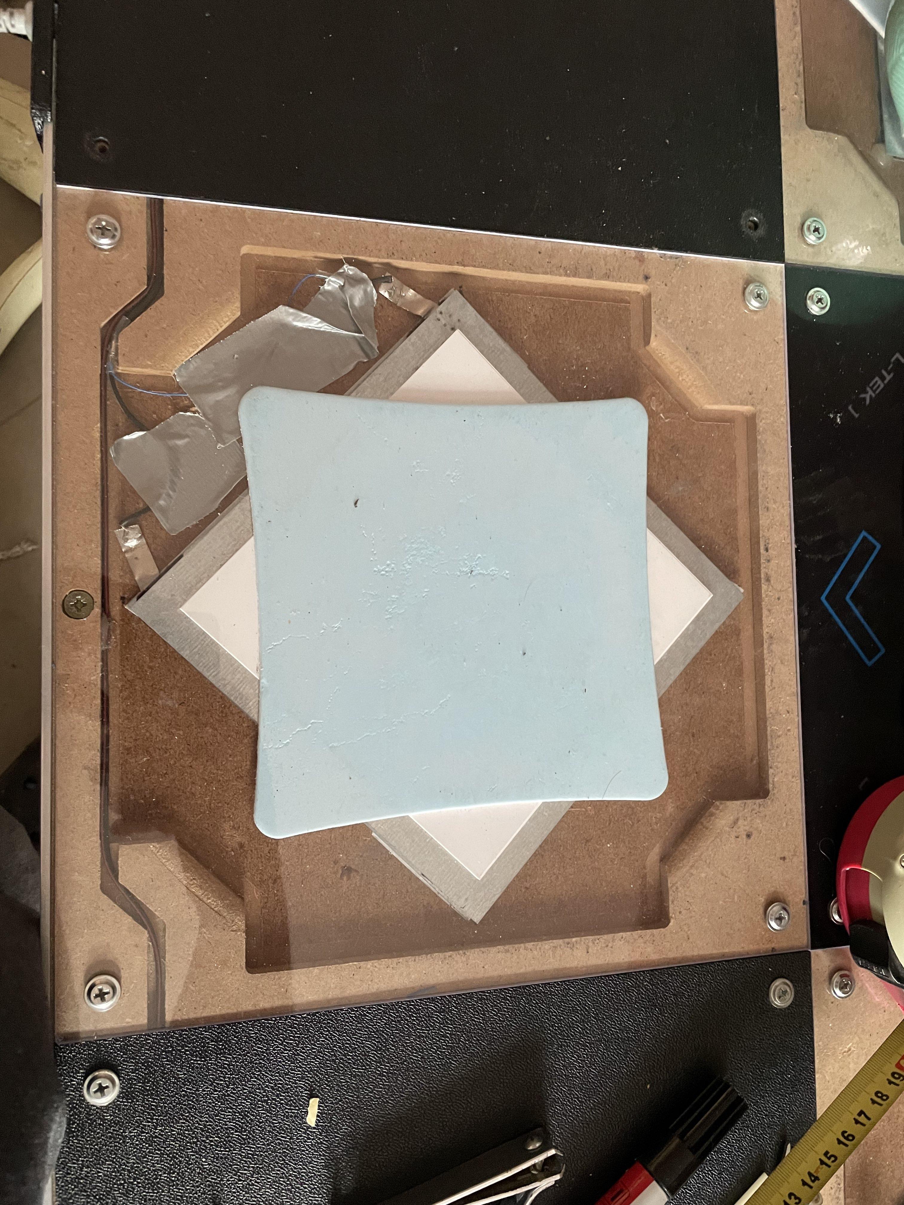
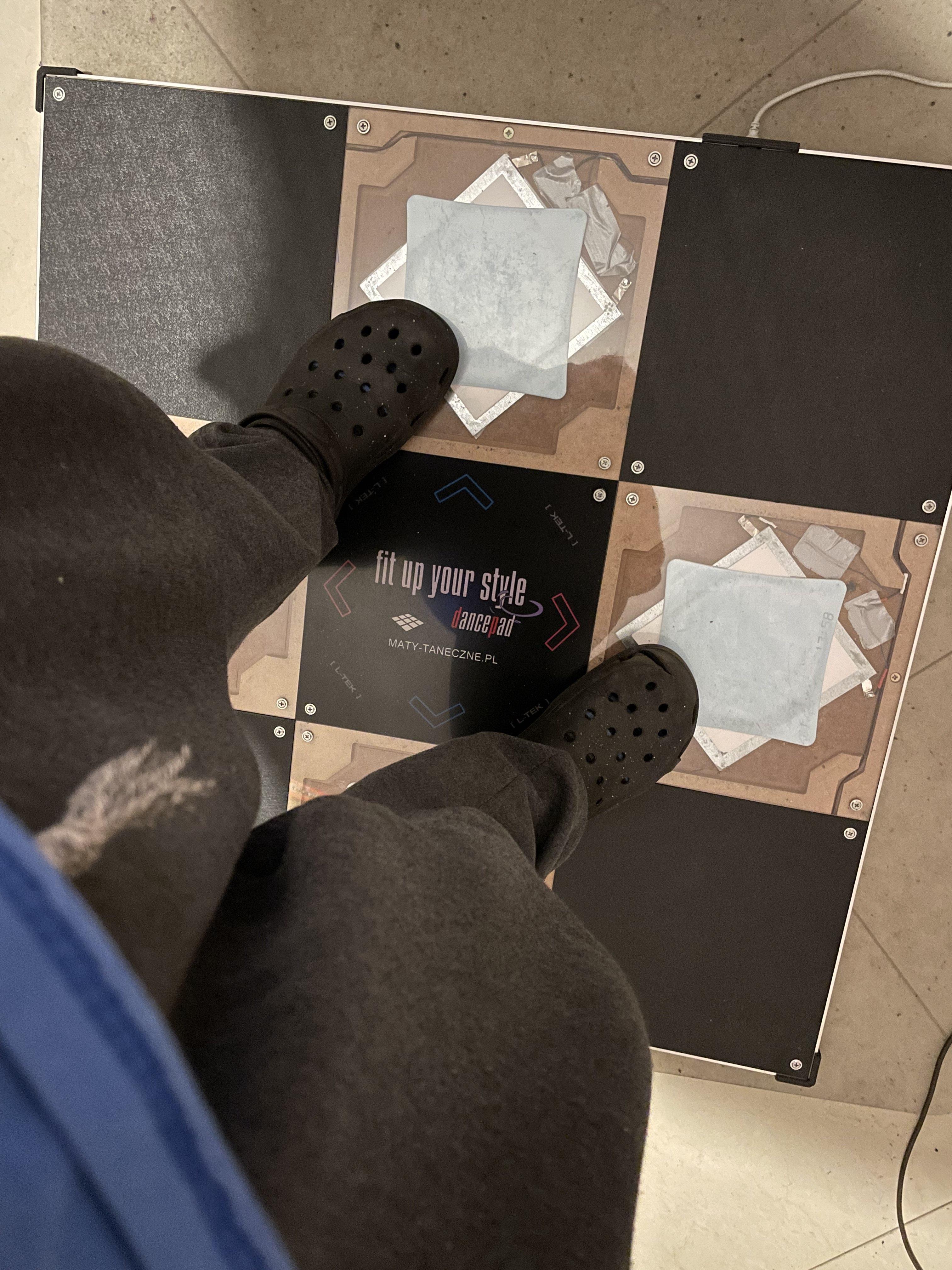
In 2010 he bought the Pad, but he wasn’t satisfied with its bracketing ability, so he sent the pad back in order to get something done about it. A couple things were done to it, like a PVC foam square being added on top of the sensor (a standard issue now), but what actually made a difference was something very simple - turning the entire sensor by 45 degrees.
This turned out to have significantly improved to ability to hit a bracket with the pad, as the actuation point was placed closer to the corners of the panels - by default the corners is where the velcro joining the two metal pieces are placed. Even the edge sensitivity gained a bit, as the active corners of the sensor were placed closer to the edge.
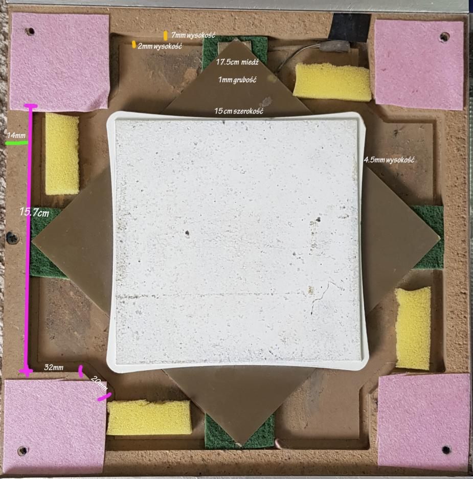
(All the foam is placed to help dampen the acryllic panel and isn’t related to the mod itself)
But why didn’t we get this in modern pads? This could be because at that time it didn’t really bring any profit to a casual player - Tech charts wouldn’t become popular in Cabinet-less parts of the world until the 2020s, and with Poland itself lagging behind (it’s 2023 and only now we are considering dropping ITG1/2 charts from the tournament pools), the mod fell into obscurity. The US community came up with its own spin on the sensitivity increasing mod by doing what Americans do best - throw money at stuff until it becomes better (the Pennymod).
But today with the International Timing League tournament many L-Tek mains (including myself) feel excluded from serious participation as they’re held back by their pads’ weak ability to hit brackets (you can hit a bracket only if you stomp REALLY hard), and the Lisek Mod is slowly gaining popularity as an alternative to the often-damaging pennymod (when incorrectly performed it can make the pennies dent the metal plates decreasing sensitivity over time).
Disclaimer
- This is not meant to be a complete guide on the modding process. I’m sure someone better suited will come up with a more robust guide in some time, and I’m only showing you the process from a simple guy’s perspective
- I am not to be held responsible for any damage you’ll do to your pad or anything else during the modding process
- Following through the guide will lead to your warranty being void
- This mod involves soldering - if you’re not comfortable doing it you could get away without it by just twisting the required cables together, but adding some solder in will help secure the connection (consider the fact that the cables will be shaking A LOT during gameplay)
Materials
- An L-Tek DDR dance pad with square sensors that are roughly 17cm long
- If your pad came with smaller sensors, you’ll have to replace them as they’re too small - you can use FR4 copper laminate but the process is outside the scope of this guide
- A Philips head screwdriver
- Used to unscrew the panels
- A pen or a marker
- Used to mark where the bottom plate will go
- A hot air gun or a hair dryer
- Used to help easen up the glue holding the metal plate in
- A flat long tool (like a flathead screwdriver)
- Used to help lift the metal plate off
- Some wire
- Used to extend the cables linking the control board to the sensors
- I used 30AWG wire because that’s what I had on hand and it works fine, IDK what’s the spec for the cables used by L-Tek
- Wire stripper (or a nail clipper)
- Used to strip wires, duh
- An adequate-sized heat shrink sleeve
- Used to secure the soldered wires
- A hot glue gun or duct tape
- Used to secure the cables
- Doublesided tape
- Used to hold down the bottom sensor plate
- (Optional) Copper tape
- Can be used to mitigate the damage done by an incorrectly-done pennymod
Steps
0. Prepare your working environment
This is not a kind of thing that you want to be doing laid down on the floor. Get your pad situated on a stable workbench or a table that you’ll be able to comfortably work on.
1. Remove the panels
Start off by unscrewing and removing the active panels. I also recommend removing the adjacent panel from which the wires are coming from, so that you’ll have an easier time manipulating them.

2. Mark the middle of the panel for later
Use the corners of the foam square to mark the the middles of the sides. This will help us align the bottom metal plate down the line.

3. Get rid of the hot glue
L-Tek is a fan of liberal use of the hot glue to keep the sensor elements in place - the corners and the small tabs attaching to the sensor plates.
Use a flathead screwdriver or a similar tool to rip them off. Pay extra attention when removing glue from cables and from velcro.

4. Remove the staples holding the tabs in
The metal tabs attached to the plates are additionally secured in place by a staple. To remove them use a flathead screwdriver or another thin tool to get under the staple (or the tab itself) and slowly wiggle it out.

5. Remove the bottom plate
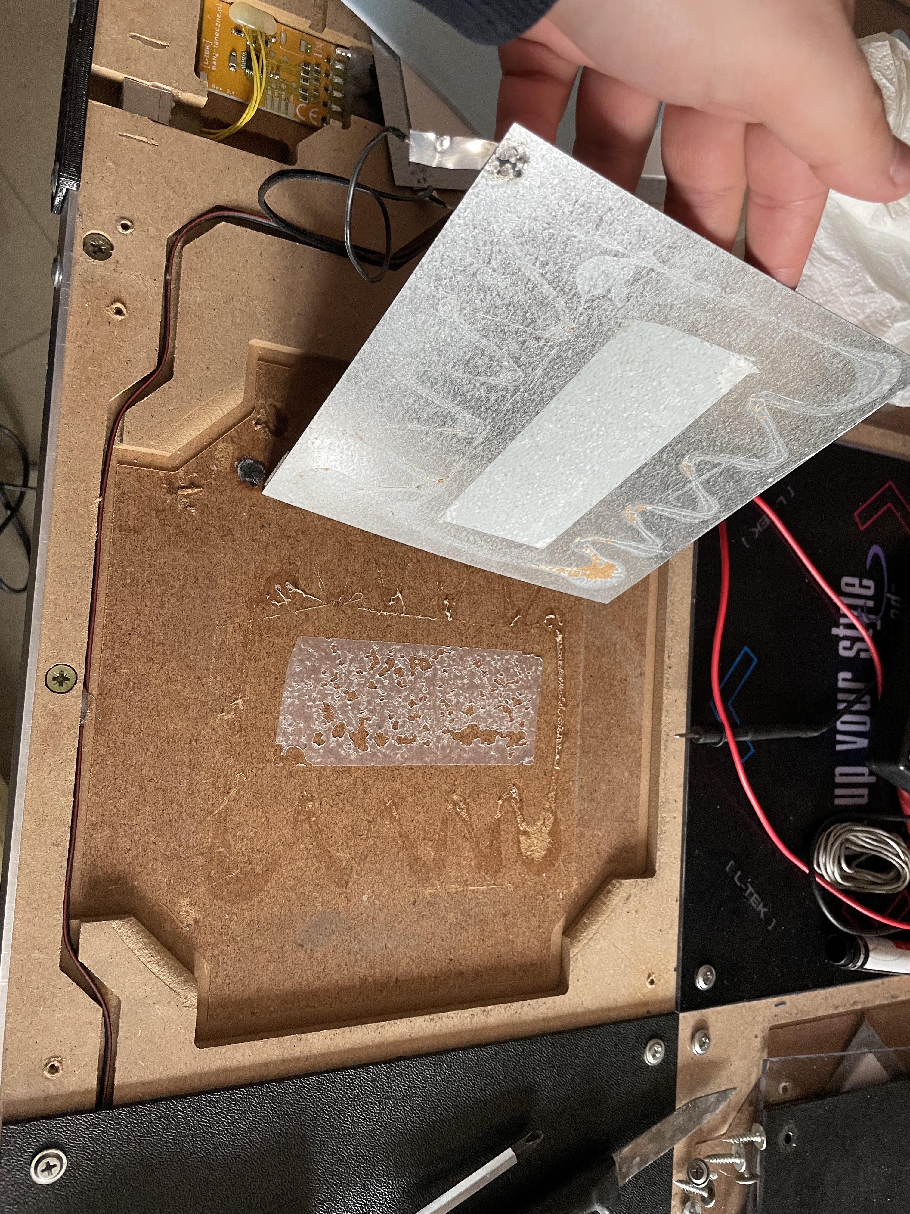
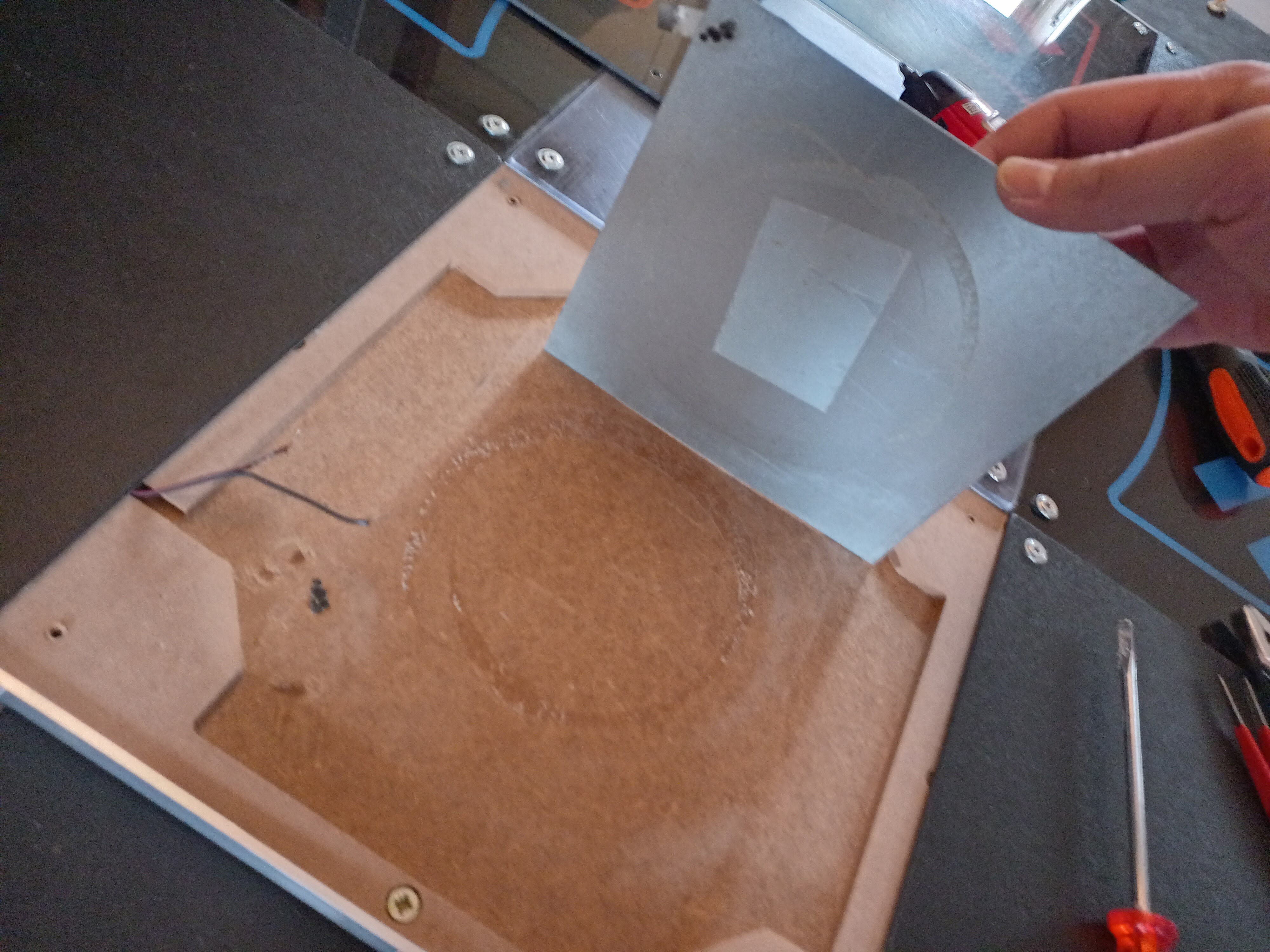
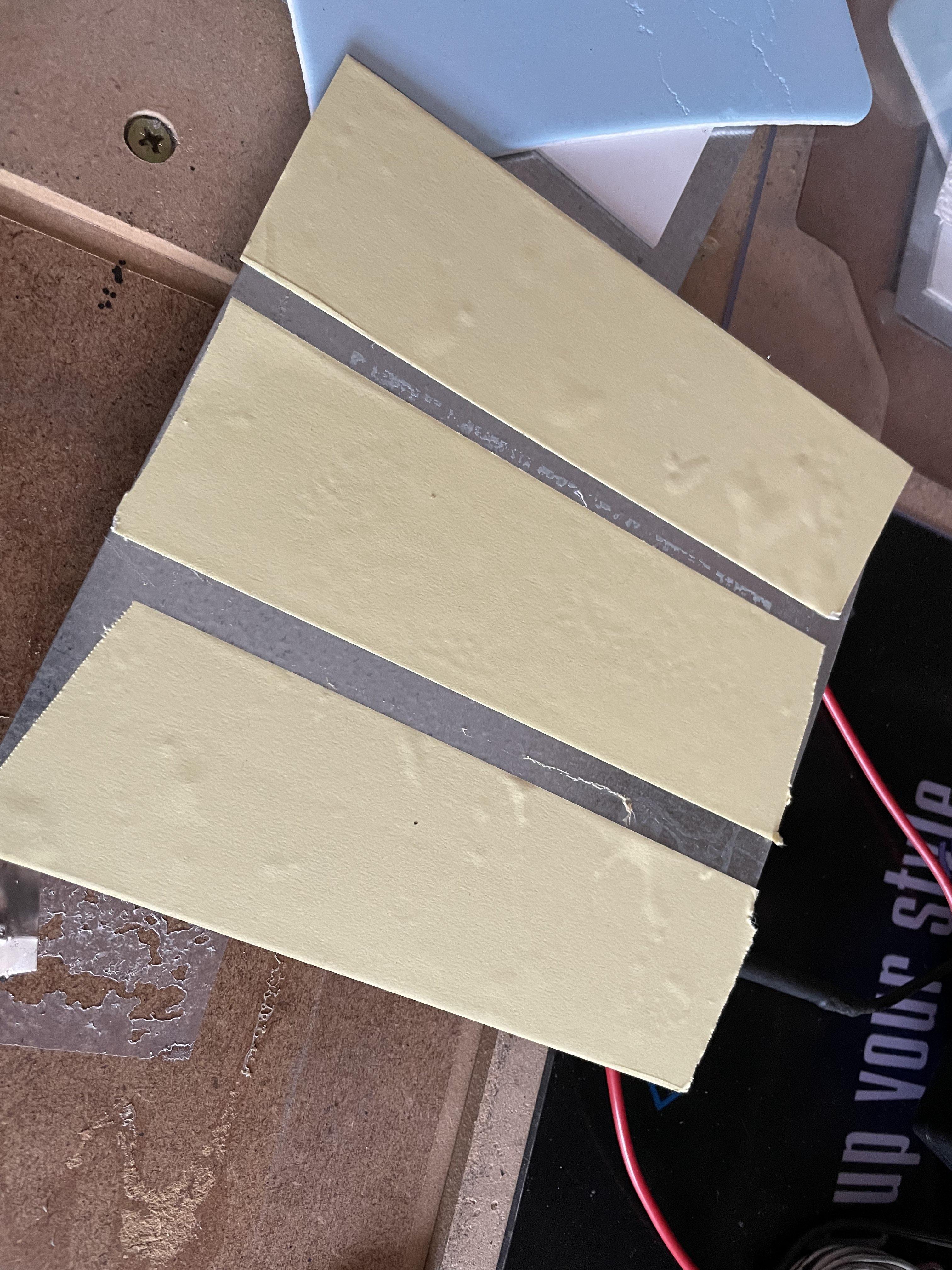
With hotglue and staples gone, you should be able to deattach the top plate. The bottom plate is held down with a combination of adhesive and doublesided tape. You’ll want to work around the plate with an air blower or a hair dryer spreading the heat evenly to the whole plate. Use a flat tool to help lift the plate off. Do your best to avoid bending it in the process, as it’s very difficult to bend it back into shape (a slight arc is acceptable).

Depending on when was your pad made, it may be attached with different proportions of adhesive and doublesided tape.
| Pad A | Pad B |
|---|---|
 |
 |
6. Test fit the plates and cut the wires if necessary
First check if you can get away with turning the plates while keeping the attached wires in the channels and not straining them. If not, you will have to extend the wire.
You want to leave around 2cm of the wire. on the plate side. Use the wire stripper to strip about 1cm of shielding from both ends.

7. Solder the extension wire
First place your plates in the desired position and measure how much extra wire you will need. Prepare a piece of wire that is a bit longer than that and strip about 1cm on each end.
Next you want to twist one end and the pad wire together (you can also form hooks with the ends and join them together).
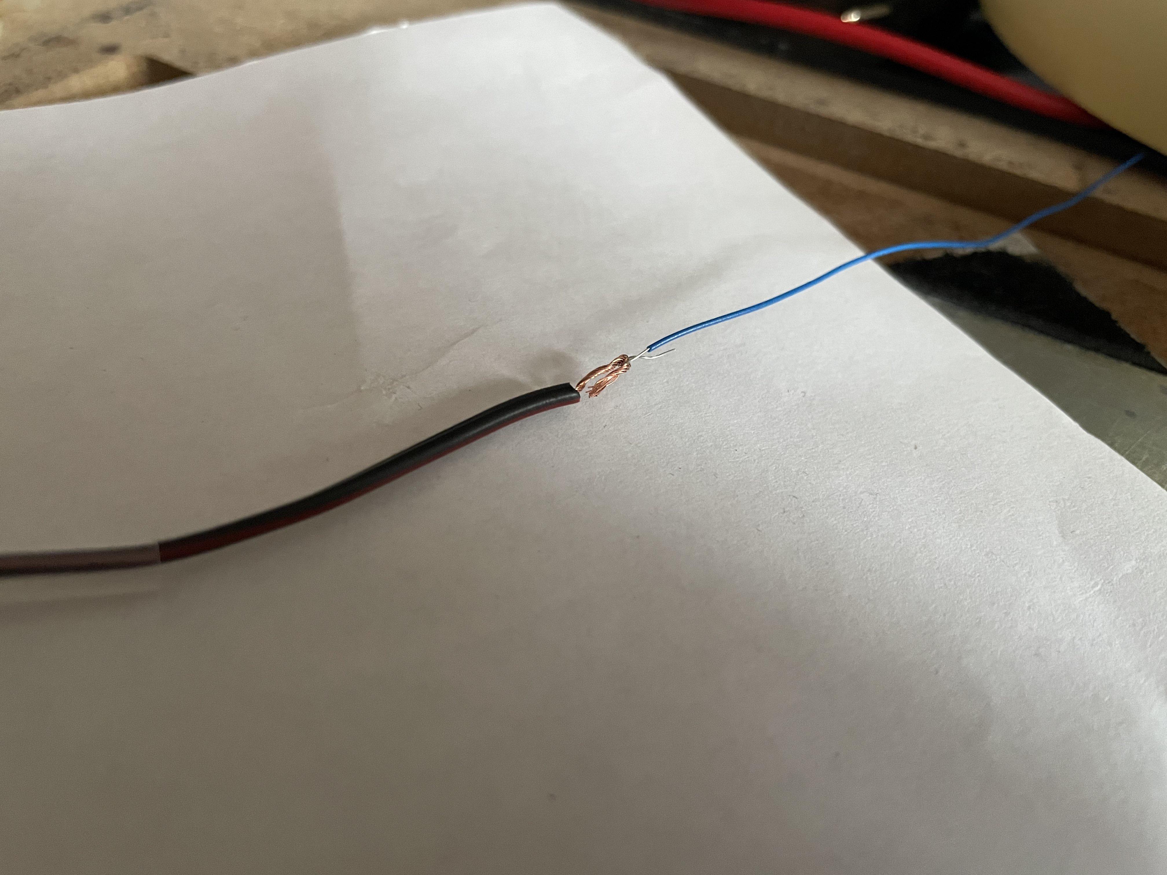
Then get them nice and straight and tin the joint with some solder. After that put on a heat shrink sleeve and apply some heat with a heat gun or the soldering iron.
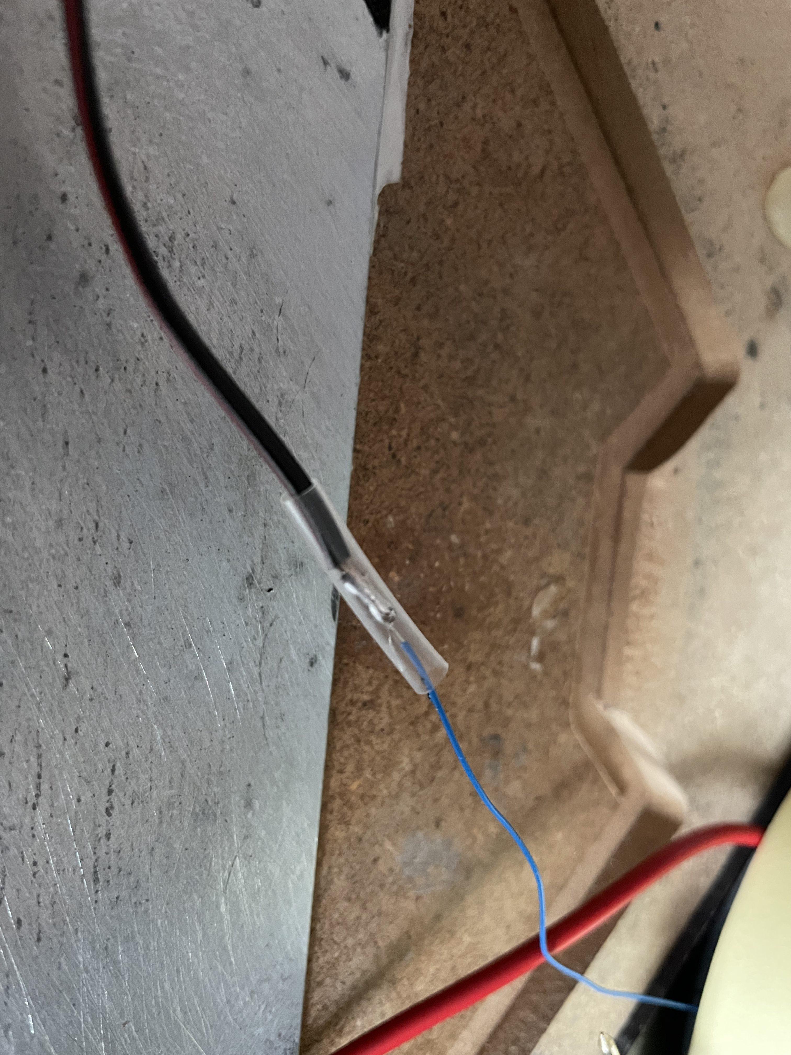
After that pull the wire through another sleeve, repeat the process for the sensor end of the wire, and put on the said sleeve.
8. Reseat the bottom plate
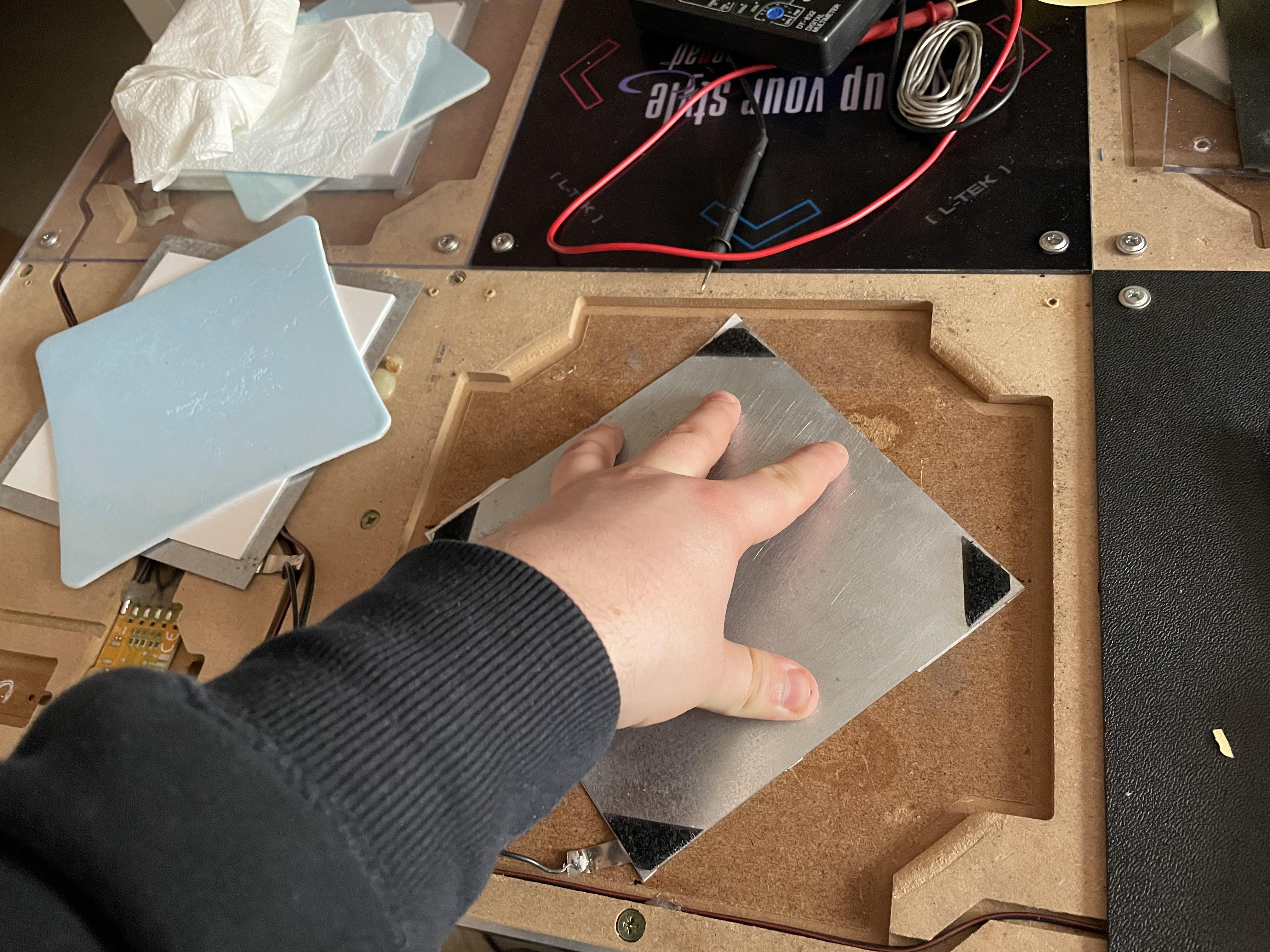
Cover the bottom of the bottom plate with doublesided tape and stick it firmly onto the pad surface using the marks you left in step 2 as guides.
(Optional) Add copper tape
If after sticking on the top plate you feel that the brackets aren’t consistent enough on both inner corners of the sensor, you may want to add some copper tape right here.
I had to use the copper tape, because in the past I’ve incorrectly pennymodded the pad causing the pennies to dent into the sensor place, which resulted in decreased sensitivity.
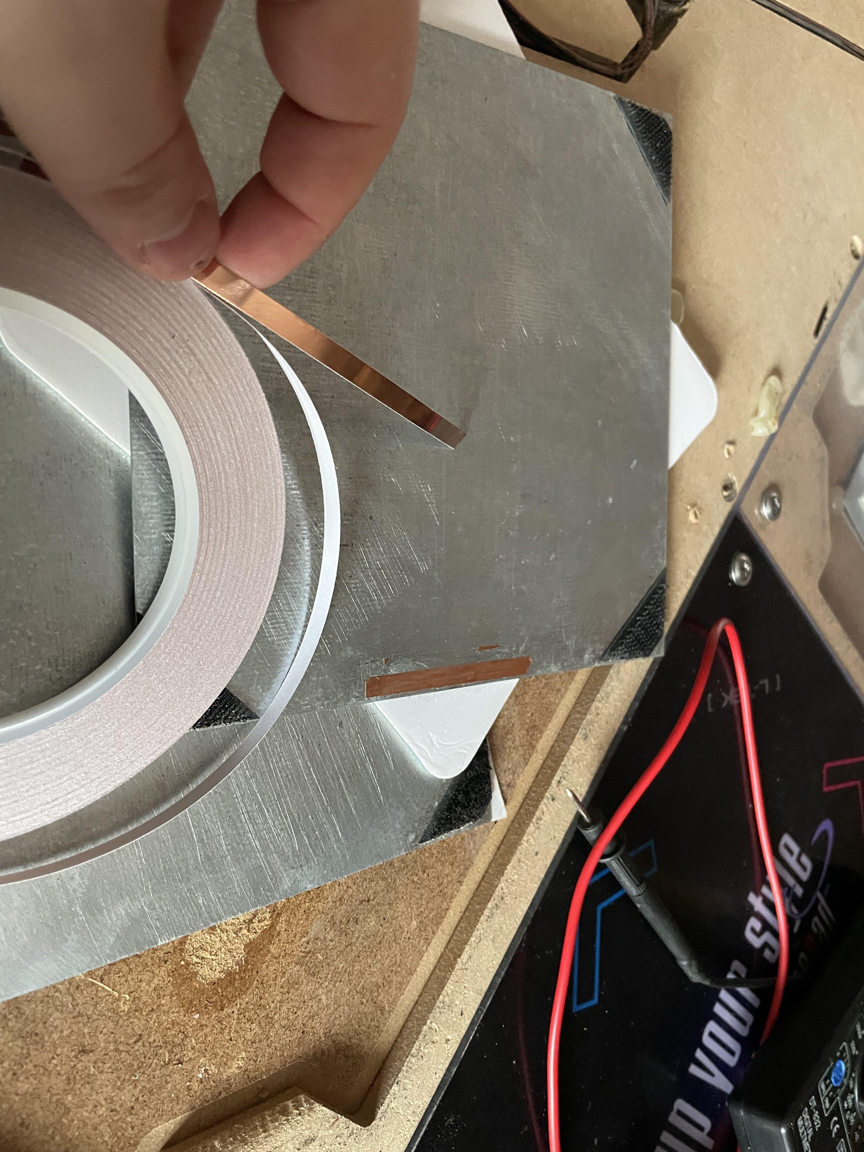
Add as many layers of copper tape as you think is needed. Personally I was aiming for actuation after pushing down the corner piece by placing my whole fingertip on the foam corner (not just the tippity tip).
9. Secure the newly installed cables
I used duct tape because I didn’t have a hotglue gun at hand.
10. Reassemble the panel
Screw the panels back on. Keep in mind that the center of the edges will stick out a bit due to how the sensor is placed currently, but the same thing happens with a pennymod.
Congrats, now you have a Polish Pad modded with Polish methods!
Additional notes
- You can swap steps 7 and 8 around if that’s more comfortable for you
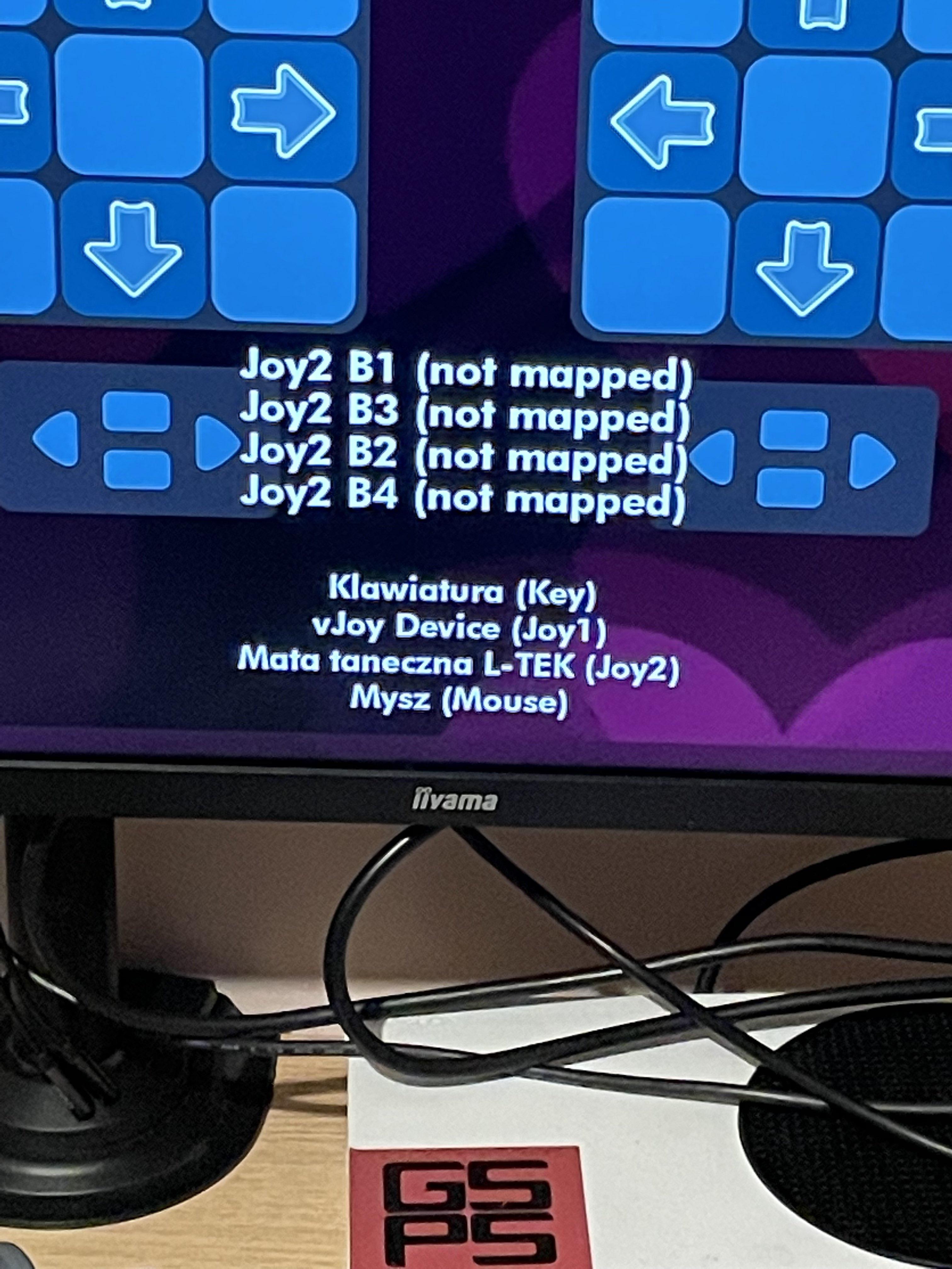
- You may want to have a computer or a laptop running an input tester nearby to check if you didn’t screw up the soldering before you put the whole thing back together. Just touch the two plates together and check if an input is registered
- If your pad’s sensor plates were separated only with hotglue in the corners, get some velcro or scouring pads and place them in the corners instead
- The clean acryllic panels aren’t premade. I went to a local polycarb fab and asked for 277mm square shaped 3mm polycarb panels and drilled the holes myself with a 5mm bit and using the old panels as guides (you can save a lot of money that way!)
- If the screws don’t stay screwed anymore, you may want to try putting a toothpick into a screw hole. You want to trim the toothpick so that it doesn’t stick out of the hole.
- If the toothpick didn’t help, try a match!
Acknowledgements
- Lisek for documenting the mod in the first place
- zibson and Thumbsy for confirming that the mod can be done with stock sensors and also providing some pics of the mod
- L-Tek for providing the ITG players with pads that while good for totally casual play, must be tinkered with in order to be competitive in 2023